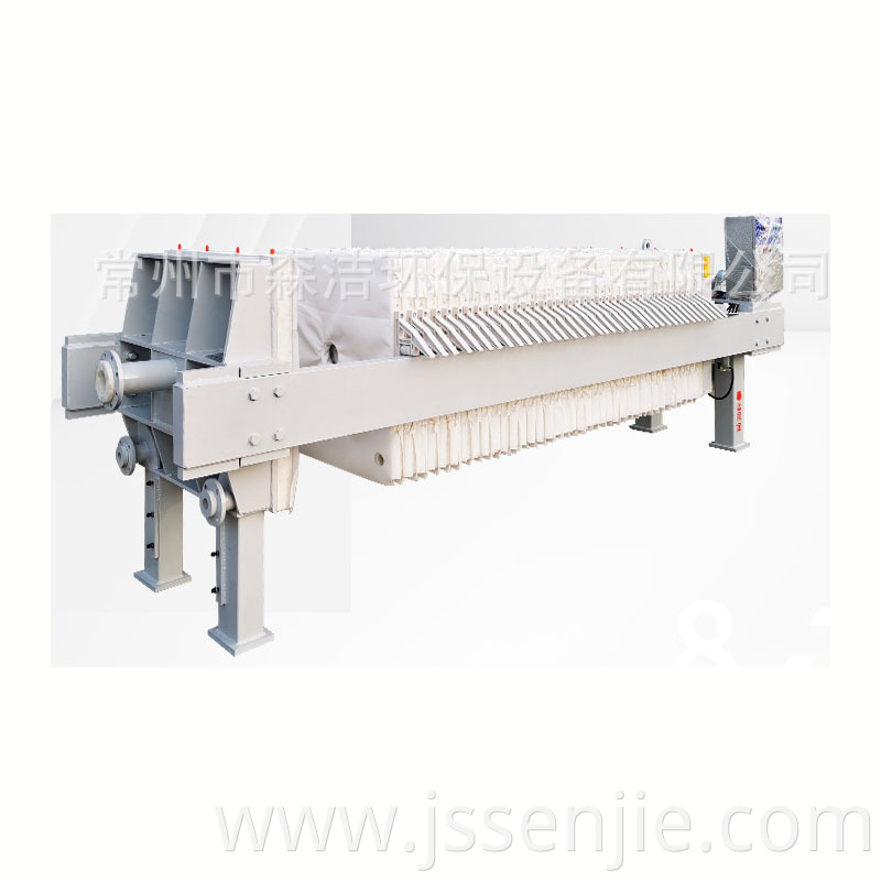
The structure of the
Filter Press consists of three parts:
folding rack
The frame is the basic component of the filter press, with thrust plates and pressure heads at both ends. The two are connected by girders on both sides. The girders are used to support the filter plate, filter frame and compression plate. To meet advanced hygiene requirements, the racks need to be covered in stainless steel. Stainless steel cladding technology can be used as a reference, and its quality can meet the needs of European customers.
A. Thrust plate: Connect to the bracket and place one end of the filter press on the foundation. The middle part of the thrust plate of the chamber filter press is the feed
There are four holes in the four corners. The holes in the upper two corners are the inlets for the washing liquid or pressurized gas, and the two lower corners are the outlets (underflow structure or filtrate outlet).
b. Compression plate: used to compress the filter plate and filter frame. The rollers on both sides are used to support the compression plate rolling on the girder track.
C. Beam: It is a load-bearing component. According to the anti-corrosion requirements of the use environment, hard polyvinyl chloride, polypropylene, stainless steel coating or new anti-corrosion coating can be applied.
The plate and frame filter press has relatively high requirements for the feed pump, which are specifically reflected in the following aspects:
During the filtration and pressure holding stages, compared with the feeding stage, the pressure that the feeding pump needs to withstand in these two stages will increase significantly, and the pump flow rate will be opposite to that, showing a decreasing trend until it closes. At this time, the press machine presses the plate frame under the action of the pump to shrink the material into a cake shape. Therefore, it is necessary to ensure that the shut-off lift of the feed pump matches the pressure requirements of the press. Failure to meet the above requirements may lead to two adverse consequences: The first situation is that the pressure of the feed pump is small and cannot meet the pressure requirements of the filter press. According to the actual demand, the moisture in the material cannot be fully squeezed, and the material cake is difficult to form, which is inconsistent with the standard. The second situation is that the pressure is too high and the filter press cannot withstand it. Its internal parts will be damaged as a result, and the filter cloth is damaged. Typical among them are
3. Unloading stage. At this stage, the filter press makes no demands on the feed pump.
The structure of the conjoined Hafranka hydraulic station consists of: motor, oil pump, relief valve (pressure regulating) reversing valve, pressure gauge, oil circuit, and oil tank. When the hydraulic compressor is compressing, the hydraulic station supplies high-pressure oil, and the component cavity composed of the oil cylinder and the piston is filled with oil. When the pressure is greater than the friction resistance of the pressing plate, the pressing plate slowly presses the filter plate. When the tightening force reaches the pressure value set by the relief valve (displayed by the pressure gauge pointer), the filter plate, filter frame (plate and frame type) or filter plate (box type) are compressed, and the relief valve begins to overflow. uninstall. , cut off the motor power, the pressing action is completed, when retracting, the reversing valve reverses the direction, and the pressure oil enters the rod cavity of the oil cylinder. When the oil pressure can overcome the frictional resistance of the pressure plate, the pressure plate begins to retreat. When the hydraulic pressing is in automatic pressure-maintaining mode, the pressing force is controlled by an electric contact pressure gauge. Set the upper limit pointer and lower limit pointer of the pressure gauge to the values required by the process. When the pressing force reaches the upper limit of the pressure gauge, the power supply is cut off and the oil pump stops supplying power. Because the oil system may leak internally and externally, the pressing force will decrease. When it drops to the lower limit pointer of the pressure gauge, turn on the power and the oil pump starts supplying oil. When the pressure reaches the upper limit, cut off the power supply. The oil pump stops supplying oil, and the cycle continues to ensure the effect of compression force during filtering of materials.


